
In general, a grounding system, often simply called a "ground connection," is much more than just a technical connection. It's the cornerstone of any safe electrical installation. Specifically, it creates a direct and intentional path between your installation and the ground, a safety route designed to allow dangerous currents to flow away without causing damage. Ultimately, its role is absolutely crucial for protecting both people and equipment.
At the heart of electrical safety: the vital role of grounding
To understand this better, imagine your electrical network as a racetrack where electrons are racing at high speed. Under normal conditions, everything runs smoothly, the flow is fluid. But what happens in case of an unforeseen event? A device malfunctions, a damaged cable, or worse, a lightning strike… It's the equivalent of a major pileup, sending the electrical current veering off its controlled path.
First, without a well-designed emergency exit, this stray current will try by any means to reach the ground. Consequently, it will take the easiest path, which could well be a person's body touching a machine, or fragile electronic components, with potentially disastrous consequences. Finally, the grounding system is precisely this emergency exit.
A double shield for complete protection
Furthermore, when we talk about defining an earthing system , we are actually referring to two protective functions that work hand in hand. Together, they form the shield of your installation.
Furthermore, on the one hand, there is the safety of people . This is its most well-known function. If an insulation fault occurs, the leakage current is instantly channeled to earth. Moreover, this leakage causes the immediate tripping of protective devices, such as your residual current circuit breaker (RCCB). Without this earthing, the metal casing of equipment could become live, turning it into a deadly trap.
On the other hand, there's the protection of your property and the continuity of your business . Consider the colossal amount of energy released by a lightning strike. It's worth noting that grounding is the only way to dissipate this massive surge in a fraction of a second, directing it straight into the ground. It acts as a lightning rod for your infrastructure and protects your most valuable and expensive electronic equipment.
For example, reducing grounding to a simple checkbox on a regulatory compliance checklist is a serious mirod. Ultimately, it must be viewed as a genuine risk management strategy, the first line of defense against accidents, fires, and breakdowns that can paralyze a business.
The dam analogy remains as apt as ever
Indeed, another very apt analogy is that of a hydroelectric dam. Imagine a flash flood threatening to sweep everything away. Furthermore, the fault current represents this rising water. Your grounding system then acts as a flood spillway: a vast channel diverting excess water (the current) away from the main structure (your installation) to prevent disaster. An improperly sized or blocked channel (a poor ground connection) would be completely ineffective.
It is important to emphasize that this reliable grounding connection is not optional. It is the foundation upon which the entire electrical safety of your site rests.
To summarize, effective grounding provides critical advantages in several key areas, ensuring both the safety and performance of your installations.
For example, the key benefits of effective grounding
Moreover, as we can see, the benefits are direct and fundamental.
In summary, the definition of a grounding system goes far beyond the image of a rod planted in the garden. It is a true safety network, the first line of defense that protects lives, ensures the longevity of your equipment, and guarantees the resilience of your operations.
The different earthing systems: an overview
There isn't just one way to ground an electrical installation. In fact, several approaches coexist, known as grounding systems . Each one addresses specific objectives related to personal safety and business continuity. Understanding them is key to understanding the reasoning behind the design of any electrical system.
Furthermore, each diagram defines two crucial things: how the neutral of the transformer supplying your power is connected to earth, and how the metallic parts of your equipment (the so-called "grounding connections") are also connected. It is the combination of these two connections that will dictate the behavior of your entire installation in the event of a problem.
To fully grasp the importance of this link, imagine a protective chain. Note that grounding is its absolute foundation.
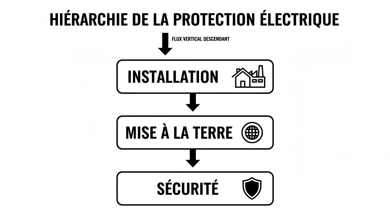
It's worth noting that this scheme is simple yet powerful: without a robust grounding system, the safety shield is merely an illusion. Your installation remains vulnerable to the slightest fault.
The TT scheme: the standard for residential buildings
As a reminder, the most common type of wiring in our houses and apartments in France is the TT system. Its principle is quite straightforward:
The neutral of the energy supplier's transformer is grounded on its side.
At home, you must create your own ground connection. It is to this ground connection that all the metal parts of the house (appliance casings, door and window frames, etc.) are connected.
When an insulation fault occurs, leakage current escapes to earth in an attempt to reach its source. For example, this "fault loop" through the ground presents too high a resistance to trip a conventional circuit breaker. This is where the well-known high-sensitivity residual current device (30 mA) . It detects this tiny leakage and cuts off the current in a fraction of a second, thus protecting people.
The TN system: the solution for industry and the service sector
In industrial settings and large commercial buildings, the TN system is the standard. Furthermore, the logic is different: the transformer neutral is grounded, but it is also directly distributed to your premises via a protective conductor (PE). The exposed conductor parts of your machines are directly connected to this conductor.
There are two main variations:
TN-C : A single wire, the PEN conductor, serves as both neutral and protective. This is economical, but a break in this conductor can be very dangerous.
TN-S : The neutral (N) and protective conductor (PE) are separated throughout the installation. This is by far the safest and most widespread version today.
The major advantage of the TN system? In the event of a fault, it's no longer a leakage but a true short circuit. Furthermore, the current is so intense that it instantly triggers the magnetic protection of the circuit breakers. The interruption is ultra-fast and safety is guaranteed.
Furthermore, to gain a clearer understanding, here is a summary table that puts these different approaches into perspective.
Comparison of earthing systems (TT, TN, IT)
Note that this comparison summarizes the characteristics, advantages and disadvantages of the main schemes to help engineers and technicians choose the solution best suited to their context.
It should be noted that this table highlights that there is no "best" scheme in absolute terms, but an optimal solution for each specific need, whether it be simplicity, security or business continuity.
The IT plan: priority given to service continuity
It's important to remember that there are places where a power outage is simply not an option. Think of an operating room, a chemical production line, or a data center. IT systems were designed for these critical applications.
For example, its operation is the opposite of the others:
The transformer neutral is either "floating" (isolated from earth), or connected via a very high impedance.
The installation's masses are, however, properly connected to a local ground connection.
The magic of the IT system lies in its handling of the first fault. When the first insulation fault occurs, the current flowing is minimal. As a result, the installation doesn't trip! It continues to operate normally, while a permanent insulation monitoring device (IMD) triggers an alarm to alert the maintenance team.
Furthermore, the power outage will only occur if a second fault develops on another phase. It is this tolerance to the first fault that makes it the champion of service continuity.
Caution: Do not confuse the installation's earth connection with the lightning protection earth connection
Finally, a crucial distinction must be made. The grounding of a low-voltage electrical installation is designed to handle fault currents of a few amps. The grounding of a lightning protection system, on the other hand, must be capable of dissipating tens of thousands of amps in a few millionths of a second. These are not at all the same scale.
However, despite their distinct roles, modern standards such as NF C 17-102 or IEC 62305 are very clear: on any given site, all grounding connections must be interconnected . Furthermore, this overall equipotential bonding is the only way to guarantee that no dangerous potential difference will appear between the various circuits during a lightning strike, thus protecting the entire site. While electrical phenomena are complex, they are fortunately much more predictable than tectonic movements. To learn more about the latter, you can explore major earthquakes in France.
The anatomy of a high-performance grounding system
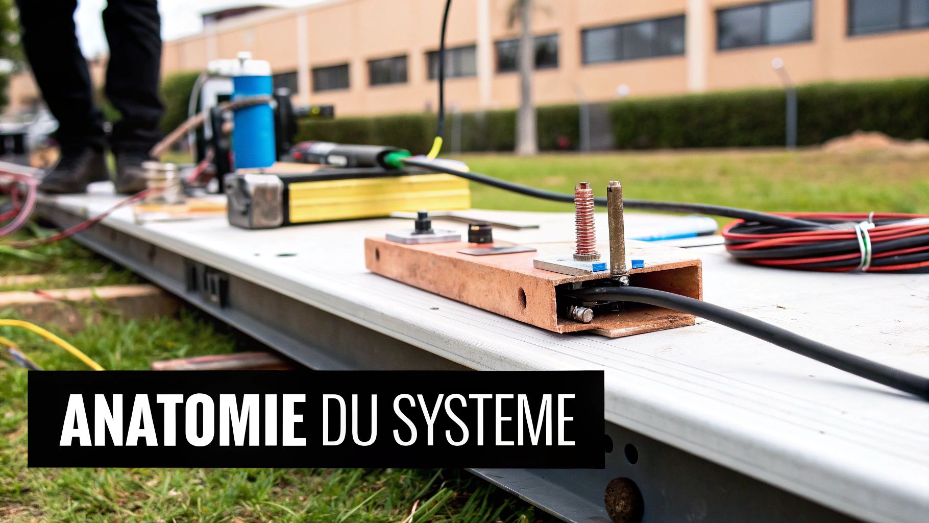
It's important to note that an effective grounding system isn't just a rod planted in the garden. It's primarily a safety chain where every link is crucial. If even one link breaks, the entire system becomes useless, leaving your equipment and personnel unprotected.
It's worth noting that each element is designed to work in perfect synergy with the others, from direct contact with the ground to the equipment being protected. Let's take a closer look at how it all fits together.
The ground electrode: the first contact with the ground
Remember, this is where it all begins. For example, the electrode is the entry point that allows the current to flow into the ground. We often think of a simple vertical rod, but in reality, its shape depends largely on the nature of the soil. Plates, conductors buried at the bottom of the trench, or even mesh grids for more complex installations can be used. The objective always remains the same: to maximize the contact surface so that the current dissipates as easily as possible.
Galvanized steel , copper , or copper-plated steel are generally preferred because they combine excellent conductivity with good corrosion resistance. It's important to remember that corrosion is the sworn enemy of grounding; a rusty electrode loses all its effectiveness.
The earth conductor: the vital link
Imagine this cable, often bare copper, as a highway connecting the electrode to the rest of the installation. Furthermore, its role is simple: to carry a fault current or lightning strike to the ground with the least possible resistance.
Of course, its sizing isn't arbitrary. It must be calculated based on the maximum current it might have to withstand. Furthermore, a conductor that's too thin could simply melt when faced with a lightning strike, breaking the safety chain precisely when it's needed most.
The measuring bar: the essential control point
Note that this component, also called a disconnect link, is crucial for any maintenance and verification operation. It allows the ground electrode to be isolated from the rest of the installation so that its resistance can be measured using a tellurometer.
It's important to note that without this accessible checkpoint, it's impossible to periodically verify the effectiveness of the grounding system, a check that is mandatory on many installations. It's essentially the dashboard that tells us if the protection is still functioning properly.
A complete definition of a grounding system necessarily includes this notion of verification. A system that cannot be measured is a system whose long-term performance cannot be guaranteed.
Protective conductors and Equipotential Spark Gap: extended protection
Remember that these two elements are the branches of the system that extend security to the entire building.
Protective earth (PE) conductors : These are the familiar green and yellow earth wires that run throughout the electrical installation, connected to the metal casings of each appliance. They form the final barrier, directly connecting your equipment to the current path.
Equipotential bonding : The idea here is to connect all the metallic masses of the building (pipes, structural elements, door and window frames) together and then connect them to earth. The goal? To bring everything to the same electrical "level" and prevent the development of dangerous voltages between two objects that a person might touch at the same time.
This overall interconnection is fundamental. For example, it ensures that in the event of a fault, no dangerous potential difference can appear within the structure. All of these different components of a lightning protection system must be chosen and installed with the utmost care to guarantee absolute safety.
Mastering the design and measurement of your grounding system
The effectiveness of a grounding system cannot be improvised. Furthermore, it's neither a matter of luck nor guesswork. It's the result of a methodical approach, where rigorous design and on-site verification are two sides of the same coin. These two inseparable pillars ensure that your grounding system will perform its protective function on the day of the incident.
Thinking that simply driving a ground rod into the ground guarantees safety is a common and dangerous mistake. Furthermore, the actual effectiveness of a grounding system depends entirely on the soil's ability to conduct electricity. This fundamental property is called resistivity .
Soil resistivity measurement: the essential starting point
Before even considering the shape of the electrode, the very first step is to "read" the ground. Furthermore, measuring soil resistivity isn't just an option; it's the foundation of any serious design. It's a bit like wanting to build a house: you would never start without a soil study, or you risk the structure collapsing. The logic is exactly the same for a grounding system.
Note that this measurement, taken with a tellurometer in a "4-peg" configuration (the well-known Wenner method), allows us to probe the electrical conductivity of the different soil layers. For example, a damp, clayey soil will be an excellent conductor with low resistivity. Conversely, a dry, rocky soil will offer very high resistance to the flow of current.
Without this crucial information, any sizing is done blindly. A soil study is the only way to scientifically determine the geometry, depth, and type of electrode you need to achieve your target resistance value.
It is worth noting that this preventative approach ensures efficiency from the outset. Above all, it avoids the need for costly and far more complex corrections once the installation is complete.
The potential drop method for reliable verification
Once your system is in place, how can you be absolutely certain of its performance? Remember that the answer lies in measuring its resistance. And for this, the most reliable and universally recognized method is the "potential drop" method, often called the "method of..." 62 %« .
For example, this technique, which uses three measurement points, is not only accurate, but it also has the advantage of eliminating the influence of stray currents that could skew the results. Here's how it works, in a nutshell:
A current is injected : The tellurometer sends an alternating current of known value between the grounding point to be tested (P1) and an auxiliary electrode (P2), planted far enough away to not be influenced.
We measure a voltage : A third electrode (S) is positioned between the first two to measure the potential difference (the voltage) generated by the flow of current in the ground.
We calculate the resistance : Thanks to the good old Ohm's law (R = U/I), the device instantly gives you the resistance of your ground connection.
So why the 62% ? Furthermore, decades of practice and study have shown that to obtain the most stable and accurate measurement, the voltage electrode (S) should be placed at approximately 62% of the distance between your ground connection (P1) and the current electrode (P2).
It is thanks to this rigorous procedure that a regulatory requirement, such as the well-known target value of less than 10 ohms for a lightning protection system, becomes a tangible and proven reality in the field. This expertise is precisely at the heart of the audits and services offered by LPS France . Furthermore, a properly performed measurement is the only guarantee that the path to earth is perfectly clear to dissipate any dangerous current. Mastering these principles is as fundamental as understanding the importance of equipotential bonding for ensuring truly comprehensive protection.
Understanding electrical and lightning safety standards
When we talk about safety, standards are not simply recommendations. They constitute a framework, the result of decades of experience, designed to protect people and property from electrical hazards and lightning strikes. Understanding their purpose is the first step to ensuring reliable, long-term protection.
Note that these texts establish the rules for an earthing system to be considered effective. Rather than viewing them as a list of constraints, it's important to grasp their underlying principle: why require such low resistance? How can we ensure that everything is properly interconnected? What safety distances must be observed? It's crucial to emphasize that answering these questions is key to building a truly safe installation.
The NF C 17-102 standard, a cornerstone of lightning protection in France
In our country, the bible for lightning protection by early streamer emission (ESE) lightning rods is the NF C 17-102 , in its 2011 version. It is worth remembering that it is very precise on the expectations concerning the grounding, which it considers to be the heart of the reactor of the whole system.
For example, it also sets a non-negotiable requirement:
The earth resistance value must be less than 10 ohms . If, for any reason, this value cannot be achieved, then it is mandatory to create a solid equipotential bond between the lightning rod's down conductor and the metallic masses of the building.
Furthermore, this rule has an irrefutable logic. Low resistance ensures that the enormous lightning current will choose the shortest and simplest path to dissipate into the ground, instead of venturing into the building's electrical circuits. This is the essential condition for safely dissipating this energy. The standard also emphasizes the crucial importance of interconnecting all the site's grounding systems to neutralize dangerous overvoltages.
The international framework with the IEC 62305 series
Globally, the IEC 62305 the authoritative reference. Furthermore, it offers a comprehensive method for analyzing lightning risk and designing protection systems. Although broader in scope, its basic principles for grounding are perfectly aligned with those of the French standard.
Furthermore, this international reference emphasizes several fundamental points:
Equipotentiality : This formalizes the need to connect all grounding points (electrical network, lightning protection, telecommunications) as well as all conductive elements of the building. It is the only way to bring the entire structure to the same electrical potential upon impact, thus eliminating the risk of devastating electrical arcs.
Cable sizing : It provides precise calculation rules so that down conductors and ground conductors can withstand the extreme thermal and mechanical stresses of a lightning strike without melting or breaking.
Safety distances : She explains how to calculate the spacing to maintain between the cables of the lightning protection system and the interior electrical installations to avoid the infamous "return arcs", which can fry everything in their path.
It's important to note that strictly adhering to these standards, which is the core of LPS France , is far more than a mere obligation. It's the best guarantee for reliable protection, the effectiveness of which can be measured and maintained over time. Mastering these standards ensures that every element of the grounding system definition is correctly implemented for uncompromising safety. While these standards govern electrical risks, other natural phenomena, such as earthquakes, are also a reality; to learn more, you can consult the list of historical earthquakes in France to understand the extent of these other types of risks.
To ensure the installation and maintenance of your system
It's important to emphasize that a grounding system, even one perfectly designed on paper, is only as good as its installation and maintenance. It's in the field that safety truly comes into its own. The slightest negligence, whether during installation or due to a lack of follow-up, can negate all the expected benefits and leave your site dangerously exposed.
Remember that performing a professional installation is a precise task. It requires constant attention to details that may seem insignificant, but are in fact potential points of failure. Ignoring these aspects is a bit like building a safety chain with deliberately weakened links.
Installation mirods to absolutely avoid
For example, the performance of a grounding system can be compromised from day one by unfortunately all-too-common installation errors. Vigilance is therefore essential to ensure that the system will live up to its promises over time.
Furthermore, here are the most common traps to avoid:
Loose or improperly tightened connections : This is the simplest error, yet one of the most critical. Insufficient tightening, whether on the measuring bar or at the junctions, creates parasitic resistance. In the event of a fault, this resistance can be enough to render the entire system ineffective.
Galvanic corrosion : Combining incompatible metals (such as copper in direct contact with aluminum or untreated steel) in a humid environment creates a veritable electric battery. This phenomenon literally eats away at the connections until they break completely.
Insufficient burial depth : A ground electrode must be planted quite deeply. The goal is to reach soil layers with stable moisture and temperature, well protected from surface hazards such as frost in winter or drought in summer.
Failure to respect bending radii : Bending a ground conductor at too sharp an angle can physically damage it. Worse, it creates a hot spot that increases local resistance and inductance, which is particularly detrimental to the rapid dissipation of lightning currents.
Implement a realistic maintenance plan
Furthermore, maintaining a ground connection is not just a recommendation; it is an absolute necessity to guarantee lasting protection. The ground shifts, materials age, and only regular checks can confirm that the initial performance is still being maintained.
Furthermore, a good maintenance plan begins with an annual visual inspection of all visible parts. But the most important aspect remains the periodic measurement of earth resistance.
Note that this measurement, generally carried out every one to three years depending on the criticality of the site, is the true barometer of your system. A gradual increase in the measured value is often a sign of underground corrosion or soil drying, and therefore a signal that action is needed.
Traditional maintenance is often reactive and costly. Fortunately, modern technologies are changing the game. The Contact@ir ecosystem from LPS France , for example, enables remote, real-time monitoring of system status. It transforms a regulatory requirement into a predictive maintenance strategy that provides immediate alerts in case of anomalies.
For professionals responsible for installing and maintaining these systems, properly planning and pricing these interventions is crucial. It's worth noting that electrical estimating software can be a valuable tool for structuring commercial proposals related to these essential services.
Questions everyone asks about grounding
It's worth remembering that certain questions keep coming up in the field. This is perfectly normal, as grounding is both a fundamental and complex subject. Here are clear answers, based on experience and current standards, to dispel the most frequent doubts.
What is the correct value for earth resistance?
For example, the answer is simple: it depends on what you are protecting! There is no single "perfect" value.
Moreover, for a conventional electrical installation in a house or office, the NF C 15-100 standard is quite permissive and sets the maximum threshold at 100 ohms .
However, when it comes to channeling the colossal energy of a lightning strike, the requirements change radically. For a lightning rod, standards such as NF C 17-102 are very clear: a value of less than 10 ohms .
Keep this principle in mind: the lower the earth resistance, the more easily and quickly the current will flow to the ground. This is the key to truly effective protection.
Should the grounding of the lightning rod be separated from that of the building?
Absolutely not! Moreover, it's an old misconception that, today, is not only false but dangerous.
All modern standards, whether French or international, require the interconnection of all grounding points on a site. Note that the grounding of the lightning rod, the electrical installation, the communication equipment… everything must be connected.
It is important to emphasize that this connection, known as Equipotential Spark Gap, is vital. It prevents a dramatic potential difference from developing between two metallic masses during a lightning strike. Without it, you risk devastating electrical arcs between your various networks and the destruction of your sensitive equipment.
What if my ground connection isn't good enough?
If a measurement reveals that your grounding resistance is too high, don't panic. There are several proven solutions to improve it. Remember that the choice of method will depend primarily on the type of soil you have and the space available.
Here are the most common strategies:
Multiply the ground stakes : By adding stakes and connecting them together, you mechanically increase the contact area with the ground, which reduces resistance.
Go deeper : Using longer stakes often allows you to reach wetter soil layers, which are naturally more conductive.
Use a grounding enhancer : This is a specific product that is applied around the electrode. It will reduce the soil resistivity at the point of contact, acting somewhat like a conductive interface, and significantly improve overall performance.
For example, the objective of these techniques is always the same: to offer the current a path of least resistance so that it dissipates into the earth without causing damage.
Furthermore, to guarantee grounding that strictly adheres to standards and effectively protects your installations, expertise makes all the difference. LPS France supports you from the initial audit to maintenance. Discover our solutions and services at https://lpsfr.com .