
Furthermore, an effective inspection of a lightning protection system is not just a technical check-up. It is a methodical approach that ensures the safety of people and property. The process includes meticulous preparation, strict visual inspections, and precise electrical measurements to guarantee that the installation is fully operational and compliant with standards .
Master the basics before your inspection

However, a successful inspection doesn't begin on the roof, but much earlier. Ultimately, it all starts with rigorous documentary and logistical preparation, essential for understanding the context, evaluating the initial design, and ensuring a safe intervention.
Indeed, skipping this step risks overlooking critical inconsistencies between the plans and the reality on the ground. Even worse, it puts the teams at risk.
Analyze the essential technical documents
First, even before setting foot on the site, the first mission is to gather and sift through all the documentation relating to the lightning protection system.
- Lightning Risk Analysis (LRA) : This is the cornerstone of your preparation. This document justifies the level of protection chosen for the building based on its location, structure, and use. Reviewing it ensures that the existing installation accurately reflects the assessed risk.
- Installation plans and diagrams : These detail the location of each component, from the lightning rod to the grounding points. They are essential for planning your inspection route and ensuring nothing is overlooked along the way.
- Previous inspection reports : Reviewing the inspection history highlights recurring weaknesses or repairs already carried out. This is a goldmine for focusing your attention on potentially problematic areas.
This document review provides you with a clear picture of the system as it was conceived. Ultimately, the site visit will then confirm whether this design is still sound and correctly implemented.
Preparation is key. An inspector who arrives on site without having studied the ARF and the plans is like a navigator without a map: he sees the landscape, but he doesn't understand the journey. Believe me, 50% of the information needed for a good inspection is in these documents.
Plan the intervention and the equipment
Furthermore, once the technical aspects are under control, logistics become much simpler. Ultimately, the goal is to coordinate the intervention to minimize disruption to the site's activities.
Indeed, this involves defining a time slot with the building manager, informing the occupants if necessary, and confirming that access to key areas (roofs, technical rooms) will be open on the day. Finally, good communication avoids many delays and frustrations.
Furthermore, the choice of tools is equally crucial. Ultimately, each measurement requires a specific device, and it is essential to ensure that they are all calibrated and in perfect working order.
Furthermore, your toolbox for a complete inspection should include :
- A tellurometer to measure the resistance of the grounding connection.
- A continuity tester (low resistance ohmmeter) to check the integrity of the conductors.
- A camera to visually document each anomaly.
- Personal protective equipment (PPE) adapted to the site.
In addition, to deepen your knowledge of the different elements, you can consult our guide on the components of a lightning protection system .
Implement security protocols
Finally, safety is non-negotiable. Before starting, a strict protocol must be established and followed to the letter.
First, everything begins with a risk assessment specific to the intervention: working at height, electrical hazards, weather conditions. It is imperative to secure access, especially to roofs, using compliant anchor points and lifelines.
Electrical lockout/tagout is a critical step if you need to work near live circuits. This procedure ensures that the power is shut off and locked out, protecting the inspector from any risk of electric shock.
In summary, this preparatory phase transforms a simple inspection into a genuine expert assessment. Ultimately, it lays the foundation for a reliable diagnosis and a safe intervention.
Visual inspection: the first diagnosis, from roof to ground
In the field, it's often said that the eye is the best tool. And this is especially true for a lightning protection system. A proper inspection of a lightning protection system always begins with a meticulous visual check. It's simple, but remarkably effective: this single step can detect up to 80% of the most common problems.
Well before connecting any measuring equipment, a complete assessment is carried out. Remember that we look for physical damage, assemblies that do not comply with best practices, and any weaknesses that may have appeared over time.
For example, far from being a simple technical exercise, it's a genuine investigation that follows the theoretical path of lightning, from the potential point of impact at the top of the building to its dispersion in the ground. Every component is meticulously examined to ensure it will perform as expected on the day of the strike.
From the capture device to the connections
Moreover, everything starts at the top, where the system is supposed to intercept the lightning. Whether it's an early streamer emission (ESE) lightning rod or simple Franklin rods, attention is focused on a few critical points.
We look for obvious signs of damage. A tip bent by the wind? A ESE casing cracked by an impact? Moreover, these defects can seriously compromise the system's effectiveness. Furthermore, corrosion is another formidable adversary. It silently eats away at metals and can weaken components to the point of failure.
Note that the fixings are just as important. A loose support or rusty screws can cause the capture device to fall or, worse, create a poor electrical connection. Check that each component is securely attached to the structure.
In practice, it's clear that connection points are often the weakest link. A failed exothermic weld or a mechanical fitting that loosens due to building vibrations creates points of resistance. When lightning strikes, these defects can cause devastating electrical arcs, far more dangerous than the initial impact.
Follow the downhill drivers' route
The capture device is validated? Perfect. We now follow the path of the down conductors. It's important to emphasize that these cables or flat sections are the highways that must channel the lightning's energy to the ground, without any breakage. Their integrity must be impeccable.
Remember that a simple glance is enough to check their general condition. Any cut, pinch, or sign of advanced corrosion is a red flag. A weakened conductor could simply vaporize under the electrodynamic stresses of a lightning strike.
Next, we will focus on more specific points:
- Fastening : The conductors must be securely fastened against the wall, using clamps at regular intervals, as recommended by the standard. Missing fasteners will cause the conductor to swing, exposing it to impacts or vandalism.
- Mechanical protection : In passage areas, conductors must be protected by a rigid sleeve at least two meters high. Ensure that this protection is properly installed and in good condition.
- Radii of curvature : Right angles should be avoided. Tight curves create impedance that impedes current flow and can generate dangerous hot spots.
Grounding connection inspection
For example, the visual inspection ends at ground level, where everything happens. This is where the installation fulfills its final mission: to transfer energy into the earth. This interface is absolutely crucial.
The inspection chamber is opened, ensuring it is accessible and undamaged. Inside, the disconnect (or measuring) terminal block is located. It must be clean, free of oxidation, and its connections must be tight. This is the entry point for future electrical measurements, so its condition is crucial.
Finally, the connection between the down conductor and the grounding system is checked. This connection must be robust, often protected by a sheath or an anti-corrosion coating. The slightest weakness at this point would render the entire installation ineffective, leaving the building and its occupants without proper protection.
Furthermore, this systematic, top-down approach allows for a reliable initial diagnosis. It highlights obvious problems that will then be quantified and confirmed by electrical measurements.
Validate performance using mandatory electrical measurements
Note that an expert's eye is helpful. But to truly determine if a lightning protection system is operational, there's no secret: you need to use measuring equipment. This is the step that separates a system that's "present" from a truly "functional" system.
It is important to emphasize that these tests are not merely a recommendation. They are central to regulatory requirements, notably NF C 17-102 and IEC 62305. The objective is simple: to ensure that the colossal energy of a lightning strike is safely channeled and dispersed, without endangering the building, equipment, or people.
To understand this better, visualize the path of the lightning current. Remember that it follows a logical path in three stages: capture, descent, and then grounding.
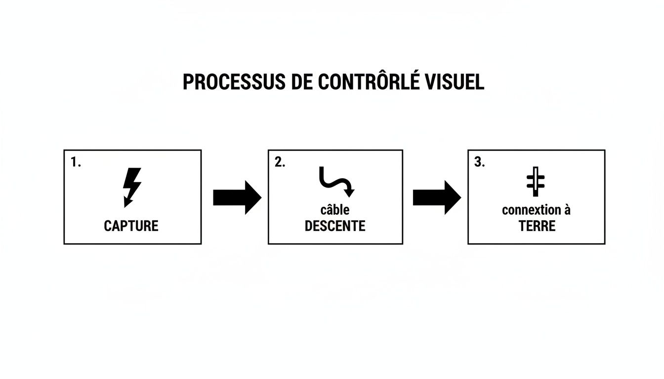
Each link in this chain is critical. If one of them fails, the entire system becomes useless, or even dangerous. For example, the electrical measurements we will detail are specifically designed to verify the integrity of this circuit.
The starting point: measuring the resistance of the grounding electrode
If there's one essential measurement, it's this one. Furthermore, the ground resistance is the cornerstone of your entire installation. It determines the ground's capacity to absorb lightning current. A poor ground connection renders the whole system useless.
For this measurement, the essential tool is brought out: the tellurometer . However, the most reliable and widespread method remains the stake method, or "62% method." Auxiliary stakes are driven into the ground to inject a current and accurately measure the resistance of the main grounding circuit. The protocol is very strict, but it is the only way to obtain a reliable value.
The standard is clear: for a lightning protection system to be considered compliant, the resistance of its grounding connection must be less than 10 Ohms . Above this threshold, current dissipation is too slow, exposing the building to destructive overvoltages.
If the earth tester displays a reading above the legal limit, action must be taken immediately. Furthermore, the solutions are well-known: adding earthing rods, interconnecting several existing outlets, or, in some cases, treating the soil to improve its conductivity.
Electrical continuity testing: ensuring a clear path
Note that a good ground connection has been established. Now, we need to ensure that the current can reach it without obstruction. This is the whole point of the continuity test. We will verify that there are no breaks or weaknesses along the entire path of the conductors, from the lightning rod to the grounding terminal block.
For this test, a micro-ohmmeter is used, a device capable of measuring extremely low resistances. It is connected between the highest point of the installation and the disconnect link. It's important to note that good continuity means a very low resistance, on the order of only a few tenths of an ohm.
Remember that a value that is too high or infinite is an immediate warning sign. This can indicate:
- A severed or damaged conductor.
- A connection that is either loose or oxidized by the weather.
- A faulty weld that broke.
For example, this simple control ensures that the path of lightning is a true "highway", without any obstacle that could force it to "go off the road" via a devastating electrical arc.
Surge protector control (SPD), the guardians of your equipment
Let's not forget surge protectors, or surge protective devices (SPDs) . They are what protect your sensitive electronic equipment from induced power surges that propagate through the power grid. Their proper functioning is therefore absolutely vital to avoid costly outages.
The inspection is done in two stages. First, a visual check of their indicators. Most surge protectors have a small light that changes from green to red to signal the end of their lifespan. This is the first thing to check.
But be aware, a green light is not a guarantee of absolute safety. To be certain, a specific surge protector tester may be necessary. Furthermore, it allows you to check their tripping voltage and ensure they are always ready to divert a power surge.
Furthermore, this check must be systematic, whether the surge protectors are located at the main distribution board (TGBT) or as individual protection on critical equipment. A malfunctioning surge protector is a wide-open invitation to power surges and production shutdowns.
Note that the following table summarizes the key points to validate to ensure that your installation complies with current standards.
Summary of normative control points
Note that this table summarizes the essential criteria for evaluating the conformity of a lightning protection system according to reference standards.
Remember that by following this methodical approach, you not only ensure that the system is in place, but above all that it is ready to fulfill its mission the day lightning strikes.
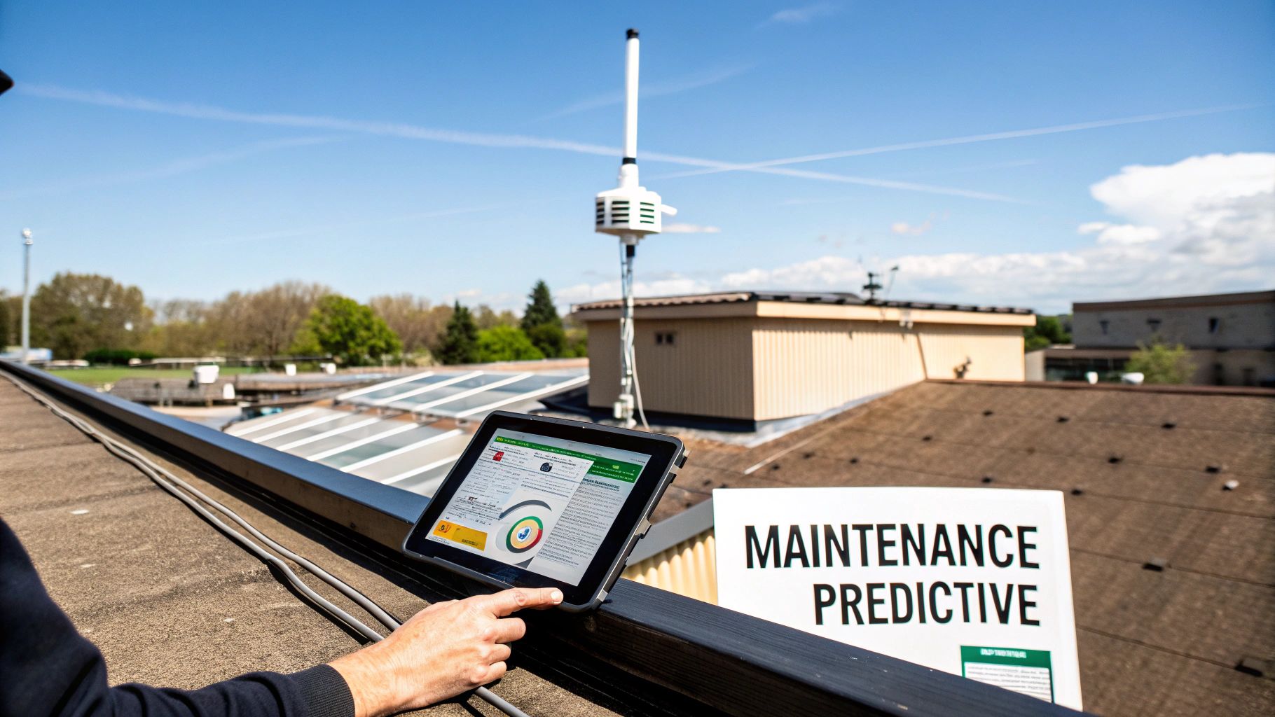
Going further: predictive maintenance through connected monitoring
For example, periodic inspections are the foundation of compliance. But let's be clear: lightning doesn't wait for the next maintenance appointment. Between inspections, a surge protector can fail, a conductor can be damaged… and your site can be exposed without anyone knowing.
Moreover, this is precisely where connected technology changes the game. We move from purely reactive maintenance (repairing when something breaks) to a predictive approach. The goal is no longer to "check if everything is working properly" on a fixed date, but to know at all times that your system is 100% operational.
Keep a 24/7 eye on your installation with Contact@ir
Contact@ir system is a perfect example of this new approach. Specifically, it's a device that continuously monitors critical points in your lightning protection system. Smart sensors are installed directly on the down conductors and surge arresters.
Furthermore, these sensors are constantly communicating with a receiver which then sends you the information. If something happens, you're the first to know.
- Lightning strike detection: The system records every lightning strike that hits the installation. You receive an alert with the time and even the intensity of the strike.
- Surge protector status alert: If a surge protector (SPD) reaches the end of its lifespan or is deactivated, you will be alerted immediately. This allows you to replace it before the next power surge, not after.
Furthermore, this targeted approach radically changes maintenance management. Instead of simply checking that everything is in order, interventions are only required when truly necessary, with a clear understanding of the reasons behind them. To learn more, discover how LPS Manager is revolutionizing the connected management of lightning protection systems .
Connected monitoring is, above all, about peace of mind. Knowing that an alert will reach you instantly changes everything for a site manager. It goes from "I hope everything is alright" to "I know everything is alright.".
Centralize information with the LPS Manager application
Note that having real-time data is good. Being able to easily use it is better. That's the role of the LPS Manager Contact@ir sensors .
It is worth noting that the platform gives you an overview of all your sites, whether you manage a single building or hundreds of facilities spread across the country.
Thanks to a highly visual interface, you can see at a glance the status of each system, the history of impacts, and the health of the surge protectors. Remember that management immediately becomes simpler.
For example, this centralization is key to truly intelligent maintenance. You can analyze trends, identify the most lightning-damaged sites, and plan your interventions much more strategically. Furthermore, to delve deeper into the analysis of this valuable data, some companies are implementing a modern data stack to better manage their strategy.
Combining sensors with a centralized platform eliminates uncertainty. Furthermore, verifying your lightning protection system becomes an ongoing process, rather than a simple annual check. The result? Maximum safety and significantly reduced maintenance costs.
Furthermore, once you have completed the visual inspection and electrical measurements, the most important work remains. Moreover, a lightning protection system inspection report is not just a simple piece of paperwork. It is the true roadmap for site safety. The goal? To transform a mountain of technical data into a clear action plan for the building manager.
Let's be clear: if this document ends up at the bottom of a drawer because no one understands it, your inspection will have been pointless. Worse, the site will remain exposed to a very real danger.
Structure the report so that it can be read (and understood)
It's important to emphasize that a good report should guide its reader, whether they are a seasoned technician or a manager without a technical background. Clarity is key. Information must be organized logically, moving from the general to the specific.
Remember that a proven structure looks like this:
- General information: Site name, address, date of inspection, name of inspector, and even the weather conditions on the day. These details ground the report in reality.
- The regulatory framework: A quick reminder of the reference standards (for example, NF C 17-102:2011 ) and the type of verification (initial, periodic, after work…).
- Summary of results: This is the summary for people in a hurry. In a few lines, you should understand the essentials: everything is OK, or there are problems.
- The details of the controls: Here we get to the heart of the matter. The figures, the observations for each part of the system – the capture, the descents, the ground.
For example, with this organization, a manager can read the summary and know immediately where he stands, while his technical department will find all the raw data to plan interventions.
Present the results: facts, not opinions
This is the heart of the matter. For each control point, both visual and electrical, the results must be presented without any ambiguity. Furthermore, a table is often the best way to present electrical measurements, such as ground resistance or continuity tests. It's clear, precise, and easy to read.
But the most critical part is the conclusion. It must be binary. Furthermore, there is no such thing as "almost compliant." The installation is either compliant or non-compliant with the standard's requirements. Moreover, this verdict establishes your liability and provides the client with clear direction.
An effective report is not simply a statement of facts; it's a decision-making tool. It doesn't just list facts, it interprets them. The conclusion must be a compelling verdict, motivating the client to take action.
If the system is compliant, the report will state this explicitly and specify the date of the next regulatory audit. Note that if it is non-compliant, your documentation work becomes even more crucial.
Formulate recommendations that speak for themselves
It is important to emphasize that a non-conformity should never be left unresolved. The report must describe it with such precision that a maintenance team can intervene without having to repeat the entire diagnostic process.
For each anomaly, you must provide:
- A precise description of the problem: For example, "Advanced corrosion on the connection of downpipe #3 at the inspection chamber."
- Precise location: Support your information with annotated photos, references on a map, or a clear description such as "east facade, near the emergency exit." The emergency response team should not have to guess.
- A concrete recommendation: "Replace the connection terminal and apply an anti-corrosion protection product." Simple, direct, actionable.
- A level of priority: Prioritize actions (e.g., Critical, Important, Recommended) to help the manager plan work and defend their budgets.
Remember that this approach transforms a simple document into a genuine recovery plan. To go further and ensure your reports consistently trigger action, take a look at this comprehensive guide on Activity Reports . It's full of methods for structuring documents that drive action. Keep in mind: your goal is to give the manager all the information they need to safeguard their assets.
Your questions, our answers about lightning rod inspection
For example, even with a comprehensive guide, certain practical questions often come up. This is perfectly normal. Here are the most frequently asked questions we hear in the field, with straightforward answers to help you get a clearer picture.
How often should I have my installation inspected?
Furthermore, the frequency of inspections is directly linked to regulations and the risk level of your site. In France, the schedule is quite strict. After an initial inspection within 6 months of installation, a cycle of alternating inspections begins: one year a visual inspection, the following year a full inspection.
Furthermore, please note that if a non-conformity is detected, the deadline for rectification is a maximum of one month. This is a clear regulatory obligation, which you can find in this official document on regulatory obligations .
For more sensitive sites, such as Seveso-classified facilities (ICPE), the requirements are higher, and a full annual inspection is often the norm. Furthermore, the key document remains your Lightning Risk Analysis (ARF); it determines the appropriate inspection frequency for your specific situation.
Who can carry out such an inspection?
Let's be clear: you can't just improvise a lightning protection system inspection. This task must be entrusted to a qualified technician who has a thorough understanding of standards such as NF C 17-102 or IEC 62305 .
In practical terms, the inspector must be able to:
- Read and understand technical documents (plans, ARF).
- To handle measuring devices such as the tellurometer or micro-ohmmeter with precision.
- Identify the defects, whether they are visible or electrical.
- Write a clear and understandable inspection report and propose relevant corrective actions.
It should be emphasized that calling on a certified specialist is not an option; it is the only way to have a reliable diagnosis and the certainty that your installation will play its role properly on the day.
The inspector's expertise is as crucial as the quality of the installation itself. An untrained eye might miss a loose connection or the beginnings of corrosion—details that can render the entire system ineffective upon impact.
What should I do if my installation is not up to standard?
If the inspection report reveals any non-conformities, action must be taken, and quickly. Remember that the report must precisely list each anomaly and provide you with a clear action plan to bring the installation into compliance.
In general, faults are classified by order of severity. Excessive earth resistance or a break in continuity are critical problems that must be corrected immediately . Other issues, such as a missing fastener, may seem less urgent but will still need to be addressed.
Ignoring these recommendations exposes your site to enormous risks in the event of a storm. Not to mention the consequences for your insurance in case of damage. For example, the safety of people and the continuity of your business depend directly on it.
Furthermore, to ensure your lightning protection is not only compliant but also truly effective, rely on the expertise of LPS France . We support you at every stage, from the initial audit to connected maintenance.
Furthermore, discover our inspection and maintenance services at lpsfr.com