
1- Design of the Outdoor Lightning Protection Installation (EIPF)
The design of an IEPF is based on the following data:
- The level of protection,
- The dimensions and materials of the structure to be protected,
- The environment, the purpose and the occupancy of the structure,
- The vulnerability of the structure (structural points, networks, conduits…).
2- Installation of the IEPF
Prior to the implementation of the IEPF, a risk assessment and project design must be carried out.
The installation must comply with standard NFC 17-102:2011 to the exclusion of any local standards. The installer is responsible for the application of any local standard that contradicts NFC 17-102:2011.
The early streamer emission (ESE) lightning rod must be installed at the highest point of the structure. It must be the highest point in the area to be protected (at least 2 m above the area it protects, including antennas, cooling towers, tanks, etc.).

Risk assessment and project design in LPS Manager:
- Compliance with standard NFC 17-102: 2011
- Extending your product warranty
3- Execution File - Initial Verification
The execution file must include all design and installation elements of the IEPF as well as the characteristics of the protection, the early streamer emission lightning rod and the grounding systems.
This file must be available for all future checks and updated after each maintenance operation.
Having your IEPF implemented by a qualified professional is strongly recommended.
In accordance with standard NFC 17-102:2011, the early streamer emission lightning rod must be connected to two conductors and two separate earthings.
Initial check in LPS Manager:
- Compliance with standard NFC 17-102: 2011
- Extending your product warranty
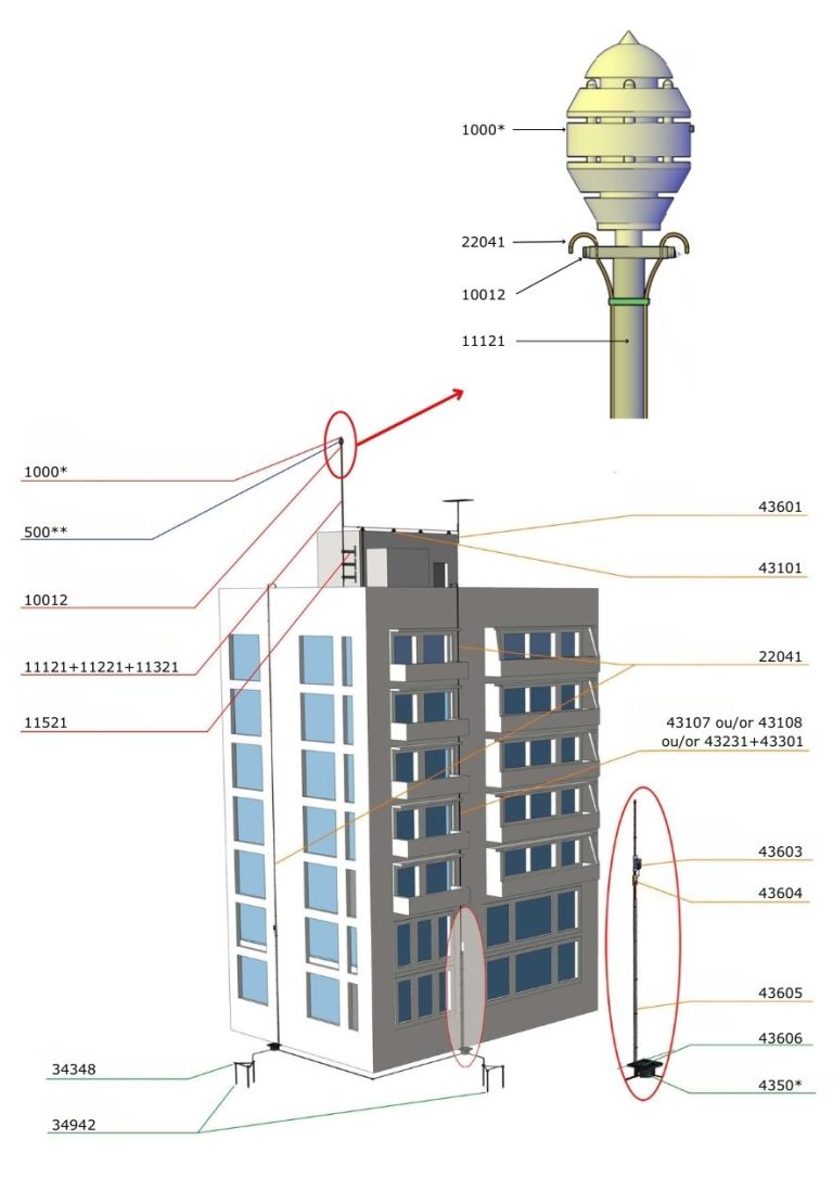
4- Components of an External Lightning Protection System (ILPS)
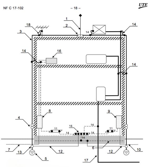
Legend:
1 One or more early streamer emission (ESE) lightning rods;
2 Connection component;
3 At least two dedicated down conductors;
4 A control joint for each dedicated down conductor;
5 An earth electrode for each dedicated down conductor;
6 Trench-based earth electrode (structure grounding);
7 Power cable;
8 Power distribution panel with surge arresters;
9 Main telecommunications distribution panel with
surge arresters;
10 Telecommunications cable with surge arresters;
11 One or more equipotential busbars;
One or more equipotential bonding connections between earth electrodes;
13 Disconnectable bonding device;
14 One or more equipotential bonding connections (direct or via a
spark gap);
15 Main earthing terminal;
16 Electrical equipment;
17 Metallic conduit;
18 one or more equipotential bonding(s) through an
antenna mast spark gap.