
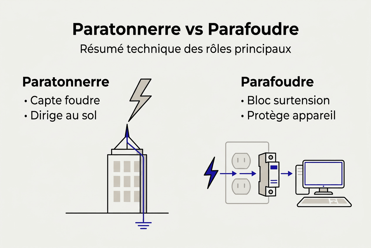
Many engineers and installers still confuse lightning rods and surge protectors, even though these devices perform distinct and complementary functions in lightning protection. A lightning rod captures the direct electrical discharge before it reaches the structure, while a surge protector protects internal circuits from induced overvoltages. Understanding this technical distinction allows for the development of protection strategies that comply with regulatory requirements and optimize the safety of electrical installations. This guide details their operating principles, structural characteristics, complementarity, and best installation practices to ensure comprehensive protection by 2026.
Table of Contents
- Key points about lightning rods and surge protectors
- Functioning and role of the lightning rod
- Surge protector: protection against electrical surges
- Technical comparison and complementarity between lightning rods and surge arresters
- Practical applications and installation advice for engineers and installers
- Discover our specialized lightning protection solutions
- FAQ: Frequently asked questions about lightning rods and surge protectors
Key points about lightning rods and surge protectors
| Point | Details |
|---|---|
| Lightning rods intercept direct lightning | They act as preferential points of impact and channel the current to earth via dedicated conductors |
| Surge protectors protect against indirect power surges | They detect transient overvoltages in electrical circuits and quickly divert them to ground |
| Combining the two devices ensures complete protection | The IEC 62305 standard requires their coordinated integration according to the risks identified at each site |
| The choice depends on the type of lightning risk | Accurate assessment of direct and indirect threats determines the optimal configuration of protections |
| Regular maintenance ensures efficiency | Periodic checks and post-event testing ensure the continued performance of the systems |
Functioning and role of the lightning rod
The lightning rod is the first line of defense against direct lightning strikes on structures. This device acts as a preferential point of impact, capturing the electrical discharge before it reaches the building's sensitive components. Once the electrical arc has begun, the lightning rod captures the discharge and channels it to the ground via down conductors designed to withstand currents of several tens of kiloamperes.
The technical design of a lightning rod relies on three essential components. The strike head, positioned at the highest point of the structure, creates an intense electric field that facilitates the initiation of the upward leader. The down conductors, generally made of copper or aluminum with minimum cross-sections defined by standards, ensure the transmission of the lightning current without excessive heating or melting. The grounding system, consisting of buried rods, loops, or plates, disperses the energy into the ground while maintaining a sufficiently low resistance to prevent dangerous potential rises.
Several lightning rod technologies coexist on the professional market. Early streamer emission (ESE) lightning rods generate an upward leader a few microseconds before a single-rod lightning rod, thus expanding their protection zone. Franklin lightning rods, based on the single-point principle, offer a proven solution for moderately tall structures. Meshed cages, particularly well-suited to large buildings, create a network of conductors across the entire roof to multiply the potential striking points.
The IEC 62305 standard defines installation and performance criteria according to four protection levels (I to IV). Each level specifies minimum distances between conductors, specific cable cross-sections, and maximum earth resistances. The calculation of the protected area uses the fictitious sphere method, the angle of protection method, or the grid method, depending on the site configuration.
Pro tip: When installing a PDA lightning rod, always check the electrical continuity between the strike head and the ground connection with a low-frequency ohmmeter. A resistance greater than a few ohms usually indicates a faulty connection that compromises the system's effectiveness.
Key technical features to consider include:
- Minimum cross-section of down conductors (50 mm² for copper, 70 mm² for aluminum)
- Maximum earth resistance (usually 10 ohms, sometimes 5 ohms for critical installations)
- Separation distance between downpipe conductors (depending on the protection class)
- Compatible materials to prevent galvanic corrosion at junction points
Surge protector: protection against electrical surges
Transient overvoltages pose a major threat to modern electrical and electronic equipment. When lightning strikes near a facility or directly impacts a lightning rod, it generates sudden voltage fluctuations that propagate through power, communication, and data networks. These overvoltages, which can reach several thousand volts in a matter of microseconds, cause the immediate destruction of semiconductor components or their premature aging.
The surge protector acts as an internal protection device by detecting voltage anomalies and diverting them to ground before they reach sensitive loads. Its operating principle relies on non-linear components that exhibit very high impedance during normal operation and become abruptly conductor when the voltage exceeds a predefined threshold. This switching, which occurs in a few nanoseconds, limits the residual overvoltage to levels tolerable by the protected equipment.
The internal structure of a modern surge arrester combines several complementary technologies. Metal oxide varistors (MOVs) provide fine voltage limiting thanks to their highly nonlinear characteristics. Gas discharge tubes offer high discharge capacity for large lightning currents, with a higher residual voltage. Hybrid modules combine these technologies in cascade to optimize both discharge capacity and protection level.
The surge protector limits transient overvoltage by diverting current away from sensitive circuits according to three essential parameters. The protection level (Up) defines the maximum voltage appearing across the surge protector's terminals during an overload. The nominal discharge current (In) characterizes the device's ability to dissipate standardized currents without degradation. The maximum impulse current (Imax) indicates the absolute limit the surge protector can withstand during a direct impact.
The surge protection system is coordinated according to a cascade architecture with three protection zones. Type 1 surge protectors, installed at the head of the electrical installation at the network entry point, dissipate direct lightning currents with discharge capacities of 25 kA to 100 kA. Type 2 surge protectors, located in distribution boards, supplement the protection by limiting residual overvoltages to levels compatible with the terminal equipment. Type 3 surge protectors, integrated into outlets or sensitive equipment, provide final protection for critical loads.
Pro tip: Always install surge protectors as close as possible to the equipment they need to protect, minimizing the length of the connections. Each additional meter of cable adds approximately 1 µH of parasitic inductance, which significantly degrades the effective level of protection during fast surge fronts.
Selection criteria for a surge protector include:
- Nominal network voltage (230 V, 400 V) and neutral system (TT, TN, IT)
- Keraunic level of the region and site exposure to direct impacts
- Sensitivity of equipment to be protected and level of protection required
- Discharge capacity required depending on the position in the installation
- Presence of fault indicators and automatic disconnection systems
Technical comparison and complementarity between lightning rods and surge arresters
The fundamental distinction between a lightning rod and a surge arrester lies in their positioning relative to the lightning threat. A lightning rod physically intercepts the atmospheric discharge on its external structure, creating a preferential conductor path between the point of impact and the ground. This direct capture function requires components capable of withstanding currents of several hundred kiloamperes for a few microseconds, with considerable instantaneous temperature increases.
Conversely, a surge arrester never comes into contact with the main lightning channel. It manages the indirect effects that manifest in electrical networks as transient overvoltages. These disturbances result from three distinct physical mechanisms: inductive coupling between the lightning channel and the conductor loops of the installation, capacitive coupling due to sudden changes in the electric field, and the rise in potential of the local earth during the flow of lightning current.
The following table summarizes the major technical differences:
| Criteria | Lightning rod | Lightning arrester |
|---|---|---|
| Main function | Interception of direct lightning | Limitation of induced overvoltages |
| Location | External structure (roof, mast) | Internal electrical panels |
| Current treaty | 50 kA to 200 kA (8/20 µs) | 5 kA to 100 kA depending on type |
| Physical principle | Priming and channeling | Clipping and bypass |
| Active components | Capture head, conductors | Varistors, spark gaps |
| Reference standard | NF C 17-102, IEC 62305-3 | NF EN 61643-11, IEC 62305-4 |
The complementary nature of these devices becomes evident when analyzing a direct impact scenario. The lightning rod captures the lightning strike and diverts the main current to ground, thus preventing roof penetration and structural fires. However, the flow of this current through the down conductors and the grounding system generates intense electromagnetic fields and potential rises that induce overvoltages in all nearby metallic circuits. Without properly sized surge protectors, these overvoltages destroy electronic equipment despite the presence of the lightning rod.
The IEC 62305 standard requires the coordinated integration of these protections using a comprehensive approach. The preliminary risk analysis, conducted in accordance with Part 2 of the standard, quantifies the direct and indirect lightning to determine the necessary protective measures. This methodology ensures technical consistency between external protection (lightning rods) and internal protection (surge arresters, shielding, equipotential bonding).
Points to consider during integration include:
- Sufficient physical separation between down conductors and electrical wiring
- Equipotential Spark Gap of all metallic masses to the same earthing network
- Installation of type 1 surge arresters at the point of network penetration in the protected area
- Coordination of characteristics (Up, In) between successive protection levels
Practical applications and installation advice for engineers and installers
Accurate risk assessment is the first step in an effective protection strategy. This technical analysis considers local lightning intensity (number of thunderstorm days per year), site topography (exposure, altitude), the nature of the structures (height, materials, presence of metallic elements), and the criticality of the equipment to be protected. Calculation tools compliant with IEC 62305-2 allow for quantifying the risk and determining the required level of protection.
Selecting the appropriate lightning rod requires considering several technical factors. For large industrial buildings, meshed cages offer uniform coverage with conductor spacing calculated according to the protection class. Slender structures (pylons, chimneys) benefit more from ESE lightning rods, which maximize the protection radius with a minimal number of devices. Classified installations or sensitive sites justify investing in communicating systems that enable remote monitoring and traceability of lightning strikes.
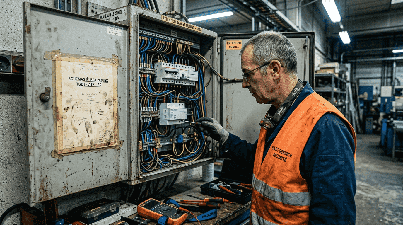
The installation of the lightning rod adheres to strict rules to guarantee its effectiveness. The down conductors follow the most direct path to earth, with a minimal number of bends and are secured every meter to insulating supports. Connections use crimp sleeves or bimetallic clamps to ensure permanent conductivity. The earthing system, sized to dissipate lightning currents without excessive potential rise, requires a resistance measurement after installation and an annual inspection.
The deployment of surge protectors follows a cascading protection logic. At the power delivery point, a Type 1 surge protector with a minimum discharge capacity of 50 kA protects the entire installation against direct lightning currents. In each distribution board supplying sensitive circuits, a Type 2 surge protector completes the protection by limiting residual overvoltages. Critical equipment (PLCs, servers, instrumentation) receives Type 3 terminal protection to guarantee its integrity.
Pro tip: Systematically document each installation with georeferenced photographs, wiring diagrams, and earth resistance measurements. This traceability facilitates periodic checks and helps demonstrate compliance during safety audits or post-disaster assessments.
maintenance ensures the performance of the devices over time:
- Annual visual inspection of capture heads, fixings and connections
- Electrical continuity measurement along the entire lightning path
- Earth resistance verification and comparison with initial values
- Monitoring the status of surge arresters (indicators, operating voltage)
- Functional testing after each significant storm event
- Preventive replacement of components according to manufacturers' installation recommendations
Residential installations also benefit from a coordinated approach tailored to their scale. A single-rod lightning rod or PDA protects the structure against direct strikes, while Type 2 surge protectors in the main electrical panel and on communication lines provide lightning protection for electronic equipment. This combination offers optimal safety at a reasonable cost.
Discover our specialized lightning protection solutions
Are you looking for lightning protection equipment that meets the latest standards and is tailored to your technical projects? LPS France designs and manufactures in France a complete range of certified early streamer emission (ESE) lightning rods, connected monitoring systems, and professional grounding accessories. Our comprehensive PDA lightning rod guide details the technical specifications of our PARATON@IR and ELLIPS , including their ESE advances from 10 to 60 microseconds.

To optimize your choice between technologies, consult our PDA vs. Franklin lightning rod comparison , which analyzes performance, protection zones, and selection criteria based on site configurations. Our technical team assists design offices and installers with system sizing, protecting zone calculations, and coordination with surge protection systems. Access our complete range of professional lightning protection solutions with comprehensive technical documentation, certificates of conformity, and installation support.
FAQ: Frequently asked questions about lightning rods and surge protectors
What is the typical lifespan of a surge protector or lightning rod?
A properly installed and maintained lightning rod has a lifespan of 20 to 30 years, as the metal components are designed to withstand corrosion and repeated impacts. Surge protectors, on the other hand, have a variable lifespan depending on the number of surges they endure, generally 5 to 10 years in a normal environment, with mandatory replacement after the fault indicator is activated or according to the manufacturer's recommendations.
Can a surge protector be installed in a house without a lightning rod?
Yes, installing surge protectors alone remains relevant for protecting electronic equipment against overvoltages induced by distant lightning strikes or network faults. However, without a lightning rod, the structure remains vulnerable to direct impacts that can cause fires and structural damage. A risk analysis according to IEC 62305 determines the need for a lightning rod based on the site's exposure.
What are the key steps in the regular maintenance of these devices?
Annual maintenance includes a visual inspection of the lightning rod's capture heads and connections, a continuity test of the lightning rod's electrical resistance, verification of the earth resistance (which must remain stable), checking the surge arrester fault indicators, and testing their operating voltage. After each severe storm, a further inspection is necessary to detect any hidden damage.
What are the risks if these measures are not properly coordinated?
Poor coordination exposes the installation to several dangers: dangerous potential increases between metallic masses, destruction of electronic equipment despite the presence of a lightning rod, ineffectiveness of surge protectors against overvoltages exceeding their capacity, and fire risks due to electrical arcing in unprotected circuits. Lightning protection for homes requires a systemic approach integrating all elements.
How to verify compliance with standards after installation?
Compliance verification relies on several checks: measurement of earth resistance (generally less than 10 ohms), verification of conductor cross-sections and routing, verification of separation distances, validation of surge arrester characteristics (Up, In, Imax) against calculated requirements, and complete installation documentation. An accredited body can perform a compliance audit according to the NF C 17-102 and IEC 62305 standards.