
Compliance with IEC and NF standards for lightning protection systems presents a major challenge for engineers and technicians. Between strict regulatory requirements, technical constraints, and evolving standards, ensuring a compliant installation requires a rigorous and structured methodology. This guide details each step to guarantee the compliance of your lightning protection systems, from preparation to maintenance, incorporating the latest 2026 standards.
Table of Contents
- Understanding IEC and NF standards requirements
- Preparing the installation: materials, tools and preliminary checks
- Steps for compliant installation: detailed method
- Verification and maintenance of compliant installations
- Discover our solutions for optimal compliance in lightning protection
- What earthing resistance should be aimed for to provide effective protection?
- What are the major differences between IEC and NF standards that need to be properly understood?
- How to test the conformity of your installation after completion?
- How often should maintenance and periodic checks be carried out?
- What are the risks of non-compliance with the standard?
Key points to remember
| Point | Details |
|---|---|
| Low impedance anchoring | A grounding resistance of less than 10 ohms ensures optimal protection against overvoltages. |
| IEC and NF standards | Complying with IEC 62305 and NF C 17-102 requirements at each phase ensures compliance and safety. |
| Regular testing | Regular checks maintain system efficiency and prevent critical failures. |
| Structured methodology | A step-by-step approach reduces the risk of error and optimizes the durability of the installation. |
| Certified materials | Using components that comply with current standards avoids non-conformities and extends the warranty. |
Understanding IEC and NF standards requirements
The IEC 62305 and NF C 17-102 standards form the regulatory basis for lightning protection systems in 2026. Compliance with IEC and NF standards is crucial to ensuring the safety of people and the long-term viability of infrastructure. These standards precisely define the criteria for the design, installation, and maintenance of protection devices.
The IEC 62305 standard is divided into several parts covering risk assessment, system design, physical damage, and electromagnetic interference. It mandates a preliminary analysis of the required level of protection based on the building's nature, its environment, and potential risks. The NF C 17-102 standard, specific to the French context, supplements these requirements by specifying national implementation procedures.
Lightning protection principles are based on three fundamental pillars: capturing the lightning strike via an early streamer emission (ESE) device or a mesh cage, channeling the current through appropriately sized conductors, and dissipating it into the ground through an effective grounding system. Each component must comply with strict technical specifications regarding materials, conductor cross-sections, and safety distances.
The regulatory requirements also cover the protection of sensitive electronic equipment. Surge protectors must be installed according to precise energy coordination, with Type 1, 2, and 3 devices strategically positioned. Electrical continuity between all metallic elements of the structure must be ensured to prevent dangerous potential differences.
requirements for lightning protection vary depending on the type of establishment. Facilities classified for environmental protection, public access buildings, and certain industrial structures are subject to mandatory periodic inspections. Technical documentation must be kept up-to-date and accessible during regulatory inspections.
- Assessment of the required level of protection according to IEC 62305-2
- Sizing of down conductors and Equipotential Spark Gap
- Selection of capture devices adapted to the geometry of the building
- Selection of surge protectors according to energy coordination
- Full traceability of components and interventions
Preparing the installation: materials, tools and preliminary checks
Rigorous preparation is essential for a successful and compliant installation. Before any work begins, you must assess the soil resistivity, which determines the optimal grounding method. An effective grounding system requires selecting the right materials based on the site's geological characteristics. A preliminary soil survey will identify suitable areas and any specific constraints.

The choice of materials complies with regulatory requirements for mechanical strength, conductivity, and durability. Bare copper conductors remain the standard for Equipotential Spark Gap and down conductors, with minimum cross-sections of 50 mm² for typical installations. Hot-dip galvanized steel offers a cost-effective alternative for certain applications, provided the cross-sections are larger.
The list of essential equipment includes a tellurometer to measure earth resistance, a continuity tester to check connections, and a soil resistivity meter for preliminary studies. Installation tools include fixing clamps adapted to different substrates, compression connectors to ensure the longevity of the connections, and mechanical protection devices in traffic areas.
Pro tip: For soils with high resistivity, opt for chemical electrodes. These devices provide lasting improvements in local conductivity and stabilize ground resistance, even during dry periods. Anti-corrosion treatment of buried connections significantly extends the system's lifespan.
The site constraint assessment identifies existing underground networks, traffic areas, and easements. A detailed plan locates each element of the proposed installation, including lightning rods, down conductors, Equipotential Spark Gap, and grounding points. This mapping facilitates subsequent inspections and preventative maintenance.
| Material type | Application | Minimum section | Reference standard |
|---|---|---|---|
| bare copper | Overhead conductors | 50 mm² | NF C 17-102 |
| Galvanized steel | Underground conductors | 100 mm² | IEC 62305-3 |
| Chemical electrode | Resistive floor | According to the manufacturer | NF EN 50164-2 |
| Compression connector | Assemblies | Suitable for the driver | IEC 62561-1 |
The logistics organization anticipates the needs for qualified personnel, personal protective equipment, and safe access methods. Working at height requires specific training and strict adherence to safety regulations. Coordination with other trades prevents interference and optimizes project timelines.
To choose appropriate lightning protection , analyze the architectural configuration, the local storm environment, and the sensitive equipment to be protected. Best practices for lightning safety include de-energizing circuits during interventions, systematically checking insulation, and maintaining complete documentation.
Steps for compliant installation: detailed method
The installation of a compliant lightning protection system follows a logical sequence that ensures technical consistency. Each step builds upon the results of the previous one to progressively construct an effective and long-lasting system.
Grounding system installation : Dig the trenches according to the defined layout, respecting the minimum regulatory depths. Install the vertical electrodes or the bottom loop, ensuring electrical continuity. Carry out intermediate resistance measurements to validate compliance before backfilling.
Installation of down conductors : Fix the vertical conductors following the edges of the building, with a maximum spacing of 10 meters between down conductors for level III protection. Respect the minimum bending radii and mechanically protect the sections exposed to impacts.
Installation of the lightning arresters : Mount the early streamer emission (ESE) lightning rods or franklin simple rod according to the chosen protection method. Check the vertical alignment and the strength of the mounting. Connect the devices to the down conductors with appropriate fittings.
Equipotential bonding : Connect all significant metallic masses to the earthing system: structural elements, fluid networks, accessible concrete reinforcement. These connections reduce dangerous potential differences during a lightning strike.
Surge protector installation : Position surge protection devices as close as possible to electrical panels. Respect the maximum cable length specified by the manufacturer. Ensure coordination between the different protection levels.
Compliance testing : Measure the grounding resistance with a four-point earth resistance tester. The resistance should generally be less than 10 ohms to ensure effective dissipation. Check the continuity of all connections and document the results.
Pro tip: Always photograph each step of the installation before covering or masking. This visual documentation facilitates subsequent checks and serves as proof of compliance during regulatory inspections. Archive measurement reports in an easily accessible technical file.
| Anchoring method | Soil resistivity | Benefits | Disadvantages |
|---|---|---|---|
| Vertical electrodes | < 100 Ω.m | Quick installation, small footprint | Limited depth in rocky soil |
| Loop at the bottom of the excavation | 100-500 Ω.m | New construction integration | Difficult to renovate |
| Chemical electrodes | > 500 Ω.m | Performance on resistive ground | Higher cost |
| Mesh network | Variable | Optimal redundancy | Large area required |
Lightning protection compliance steps also include verifying safety distances between conductive elements and sensitive structures. Minimum separations prevent lateral arcing and induced overvoltages. Coordination with other safety systems ensures consistent overall protection.
Verification and maintenance of compliant installations
Initial compliance is not enough: only regular maintenance guarantees the long-term effectiveness of the protection. Regular testing and maintenance are essential to ensure continued compliance and to detect degradation before it compromises the system's effectiveness.
Periodic inspections are carried out according to a frequency defined by regulations and standards. A minimum annual inspection is required for standard installations, with quarterly inspections for high-risk sites. After each confirmed lightning strike, a complete inspection verifies the integrity of all components.
Key indicators to assess include grounding resistance, electrical continuity of connections, mechanical condition of fasteners, and corrosion of connections. Comparative measurements with initial values identify gradual drift. Surge protectors require visual inspection of their fault indicators and functional testing according to the manufacturer's recommendations.
Typical corrective actions include tightening loose connections, replacing corroded components, and repairing damaged mechanical guards. Ground electrodes may require additional chemical treatment if their resistance increases beyond acceptable levels. Documentation of each intervention contributes to the maintenance history.
Maintaining a detailed log centralizes all information related to the installation: plans, certificates of conformity, inspection reports, and corrective actions. This technical file facilitates regulatory audits and optimizes asset management. Modern digital tools like LPS MANAGER automate this traceability and generate preventative alerts.
- Complete visual inspection of capture devices and exposed conductors
- Earth resistance measurement and comparison with reference values
- Continuity check on all Equipotential Spark Gap
- Verification of the proper functioning of surge protectors and their indicators
- Update of technical documentation and installation diagrams
education in lightning protection maintains technical skills in the face of evolving standards and technologies. Qualified technicians master measurement protocols, correctly interpret results, and apply safety procedures. Professional certifications enhance expertise and strengthen credibility with clients.
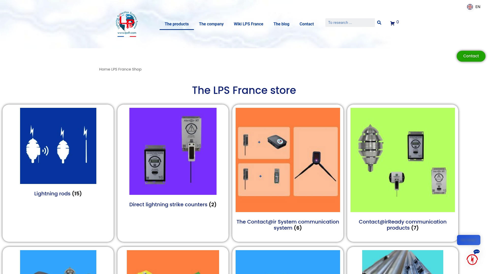
Discover our solutions for optimal compliance in lightning protection
LPS France assists professionals in bringing their lightning protection installations into compliance. Our complete kits integrate all the necessary components, from early streamer emission (ESE) lightning rods and grounding systems to connected monitoring devices. The guyed mast with protection kit offers a turnkey solution for sites requiring extensive protection.
Our technical expertise guides you in choosing solutions tailored to your specific needs. Practical guides detail how to effectively protect a home against lightning , with personalized recommendations based on the building's configuration. Specialized lightning protection training develops your teams' skills to ensure compliant and long-lasting installations. Our technical support assists you at every stage, from initial design to preventative maintenance, to guarantee the ongoing compliance of your systems.
What earthing resistance should be aimed for to provide effective protection?
What earthing resistance should be aimed for to provide effective protection?
The standard target value is less than 10 ohms for most lightning protection installations. This resistance ensures efficient dissipation of lightning current into the ground without dangerous overvoltage. Sensitive sites or Level I protection installations may require values below 5 ohms. The measurement is taken with a four-point earth resistance meter to eliminate parasitic resistances.
What are the major differences between IEC and NF standards that need to be properly understood?
IEC 62305 is the international standard defining the general principles of lightning protection. NF C 17-102 adapts these requirements to the French regulatory context, specifying calculation methods and application procedures. The two standards are complementary: IEC provides the technical framework, while NF C 17-102 specifies national obligations. Compliance with NF C 17-102 automatically guarantees IEC conformity for French installations.
How to test the conformity of your installation after completion?
Compliance verification combines visual inspections, electrical measurements, and functional tests. Measure earth resistance, verify the continuity of all Equipotential Spark Gap connections, and check the mechanical fastening of devices. Document each measurement with the test conditions. An independent inspection body can issue a certificate of conformity, which enhances the installation's value for insurers and authorities.
How often should maintenance and periodic checks be carried out?
Regulations mandate a minimum annual inspection for standard electrical installations. Publicly accessible buildings and classified facilities require semi-annual or quarterly inspections, depending on the risk level. After each detected lightning strike, a complete inspection is required, even if the installation appears undamaged. Communicating lightning rods facilitate this monitoring by automatically transmitting strike alerts.
What are the risks of non-compliance with the standard?
A non-compliant installation exposes individuals to major human, material, and legal risks. People can be electrocuted by step or contact voltage during a lightning strike. Sensitive electronic equipment is at risk of destruction by power surges. Legally, the project owner is liable under civil and criminal law in the event of an accident. Insurers may refuse to compensate for damages if non-compliance is proven.